Hello guys. I’m here to share a bit of my findings for the past 5 months. I am currently assigned to the robotic part and the automation process of the project. When I was first assigned to the project, my first task was to design a “Conveyor Belt Tracking System” for our OMRON Delta robot which at that time can only do a simple pick-and-place task. Thus, the objective of this post is to explain the entirety of the tracking system.
(Note: This will be a super long post due to some mathematical stuffs. You have been warned.)
INTRODUCTION / OVERVIEW
In the project, the client wants to automate the process of picking foreign objects from their durian paste which is done manually by hands. The main idea for the automation process is, to spread the durian paste on a conveyor belt, use camera(s) to detect the foreign objects and have robot(s) to pick them up. Here, the feature to track down these objects is indispensable for the robot to precisely pick all the objects after they have been detected by the camera. This feature helps in localizing the coordinates of the objects relative to the robot’s base frame in real time and ensure no object is missed.
The conveyor belt tracking system main function is to track all the detected objects on the conveyor belt in real time as they move along from the camera field of view towards the workspace of the delta robot.

To keep track the unit distance movement of the conveyor belt, an incremental encoder needs to be installed along with the conveyor belt. We can also use absolute encoder in this case but incremental encoder is preferred due to the fact we only need to track the movement of the belt, not the exact position of the conveyor belt. In fact, incremental encoder is much cheaper than absolute encoder!For further reading about encoder type, you can click the link below:
Thus, we can conclude the system input and output components to be:-
Input:
- Camera : To detect foreign objects on the conveyor belt using our trained model.
- Encoder : To keep track and count the movement distance of the conveyor belt at any time.
Expected Output:
- The movement of Delta robot picking up all the detected objects as they arrive within the picking range of the robot.
In truth, we will also need PLC unit to integrate all the components mentioned above. But I will leave that explanation for later post since I want to focus on the tracking part only.
ROBOT COORDINATE SYSTEM
Before we delve further into how the tracking system works, we will need some basic understanding about Robot Coordinate System.Robotic systems are generally defined as Cartesian coordinate systems, which contains 3 members; X-axis, Y-axis and Z-axis. There is also Rotation coordinate system which refers to the rotation motion and joint’s degree of robot to function. However, we will only explore the Cartesian coordinate system since this format is easier to use/understand and more popular in the industry. Though, you might need to know both formats if you wish to be a robot developer.Below are some terms used in the system that you need to know:

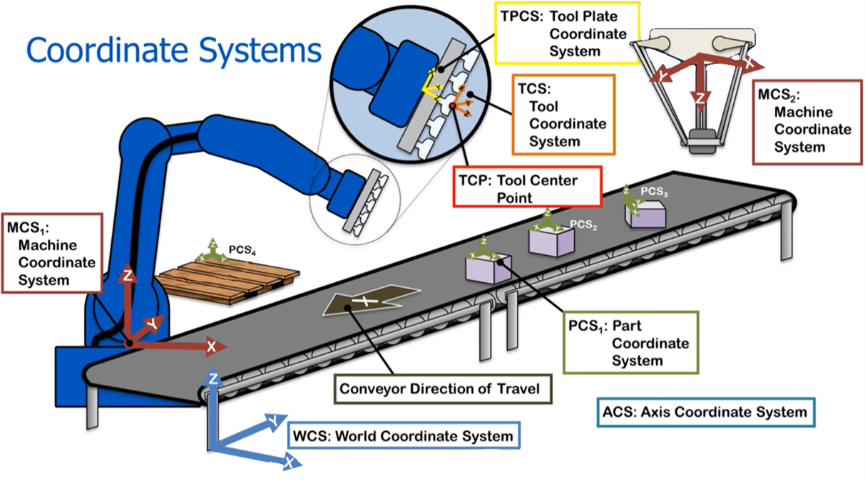
World Coordinate System (WCS)
A coordinate system that can exist anywhere in the world, but usually is defined by the user/developer. You can literally place WCS anywhere in your room/factory as long as it makes it easier to describe the position of other objects/items in that particular space. A normal practice for the origin placement is at the corner of a room OR at the edge of a group.
Machine Coordinate System (MCS)
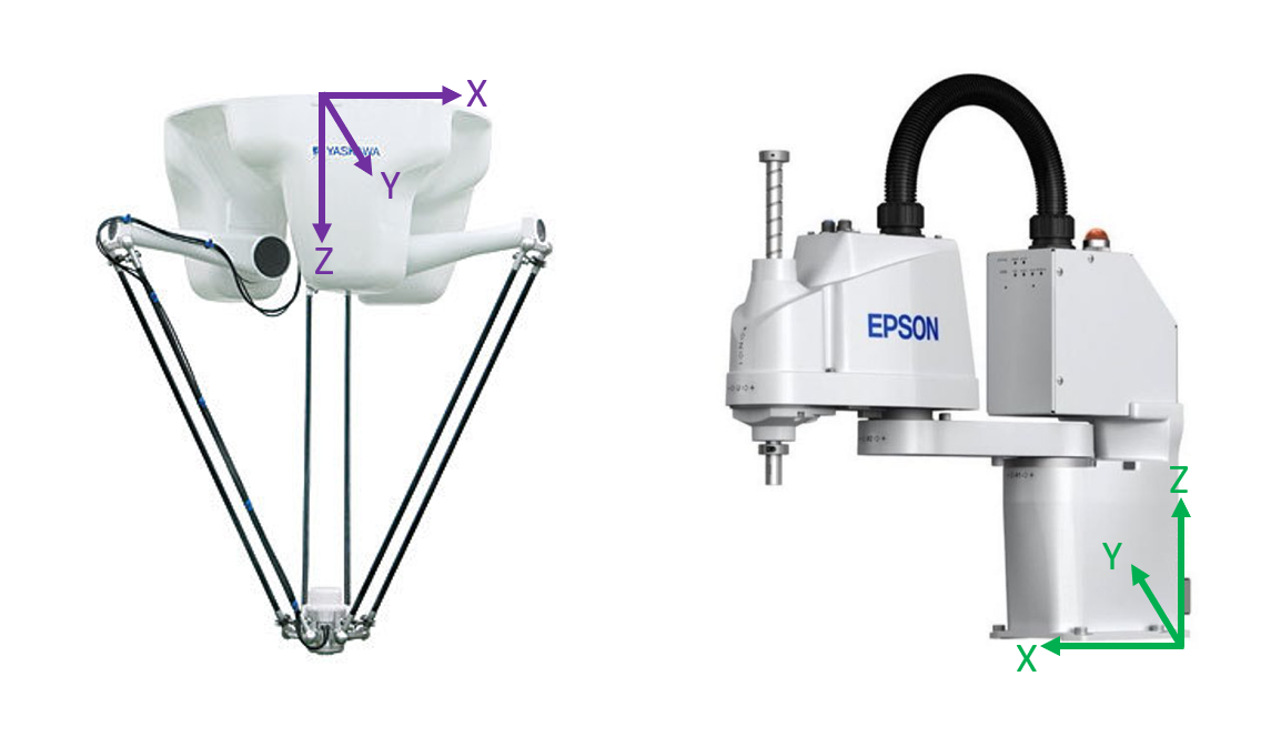
Also known as Robot Base Frame Coordinate System. This is the most important coordinate system which all other coordinate systems will be referenced to. It is also important for the developers/ programmers where they would implement their codes based on this coordinate system. For the place of origin, usually MCS is placed at the base of the robot and it is worth to note that different type of robot have different base. For example, a Delta robot’s base is at the top center of the robot and a SCARA robot’s base is at the bottom.
Part/Workpiece Coordinate System (PCS)
Referring to the tracked objects/workpiece that move along on the conveyor belt. In some application, the orientation of the parts is essential for assembly processes. This is not true for our application where we only want to pick/suck the foreign objects regardless of their orientation.
Tool Coordinate System (TCS)
Literally the position of the end-tool tip of the robot. If you notice, usually there will be some kind of mechanism added at the end of a robotic hand; either it is a gripper or a vacuum. This helps the robot to perform their tasks and usually needs a little bit of offset when we are referring to the robot base frame.If you are a hardcore robotic developer, then the term ”Forward Kinematics” and ”Inverse Kinematics” will sound familiar to you and this is where you would apply your knowledge to transform TCS with respect to the Robot base frame (I’m skipping the explanation for this part because it is too long).Luckily for us, OMRON has provided ACE software that automatically calculates everything. You only need to refer to the MCS only. TCS is important for us to get the Tool Center Point (TCP).
COORDINATE TRANSFORMATION MATRIX
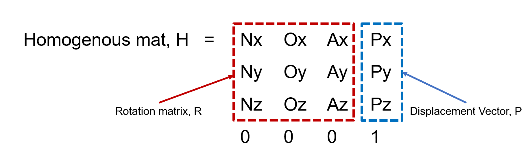
This is where the fun begins. Coordinate Transformation Matrix is basically the matrix that describes the change of orientation in a coordinate system from one frame to another frame. It consists of a 3x3 rotation matrix and 3x1 displacement vector which describe rotation transformation and translation transformation. The size of the matrix is 4x4 for a 3-Dimension case.Another name for this matrix is Homogeneous Transformation Matrix which is more frequently used and popular. Keep in mind this matrix is universal to be used in any coordinate transformation cases, whether in a forward-kinematics derivation or a normal coordinate transformation operation.
OPERATIONS BETWEEN TRANSFORMATION MATRIX
In order to form a complete homogenous transformation matrix, all the required operations to transform frame A to frame B are needed to be solved together. These small operations are called ’Transformation operation‘.For this part, there are some small tricks on how to perform operations between matrices when you have more than one transformation operation. In short, there is some rules/orders that you need to follow before performing operations on the matrices.These are called ”Pre-multiplication” and ”Post-multiplication“.
- Pre-multiplication: You should apply pre-multiplication for transformation operations that refers to fixed frame / original frame (x, y, z frame). To make it simple, these transformation operations are put to the left side of the base matrix. If you have multiple pre-transformation operations, then the last transformation will be placed to the most left of the base matrix.
- Post-multiplication: Post-multiplication is applied to all transformation operations that refers to the moving frame / new transformed frame (n, o, a frame). You put all of them the right side of the base matrix. If you have multiple post-transformation operations, then the last transformation will be placed to the most rightfrom the base matrix.
To give you a rough idea, I have made a sample question for this part.
Question:
A point P in space is defined as PB = [2,3,5] relative to frame B, which is attached to the origin of the reference frame A and is parallel to it. Apply the following transformations to frame B and find PA:i) Rotate 90° about the x-axisii) Then, rotate 90° about the moving a-axisiii) Then translate 5 unit about x-axis, 3 units about the y-axis, and 6 units about the z-axis.
Solution:
To solve this, we need to rearrange the transformations order in their rightful place. From the question above, we know that we have 2 pre-multiplication operations and 1 post-multiplication operation. Remember; for the pre-multiplication, the last transformation will be the most left. Thus our order is:
PA = Trans(5,3,6) . Rot(x, 90°) . Rot(a ,90°) . PB
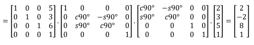
(Note: You need to do the “Dot product” starting from the most right pair and then repeat the process until the last left matrix.)
If this explanation is not enough, here I attached some of my references that might help you to get the whole picture.Reference 1: A blogpost by a lecturer explaining about robotic coordinate system.Reference 2: Another blogpost by a professor but this one with some Python code example.Reference 3: A lecture note on the introduction of homogenous transformation.
OPERATIONS NEEDED TO DEVELOP THE TRACKING SYSTEM

There are 3 main parts that make the pillars of the tracking system. These parts are literally the interactions and transformations needed between the components in the tracking system. This post will only cover a scenario that involves a camera, a belt conveyor and a robot. You can definitely add more components inside the tracking system i.e. adding more robots and cameras. The basic will be the same albeit more complex operations will be needed to compensate for the addition of more components.
1. Camera to Conveyor Belt Transformation (B1)
There is a difference between the orientation of camera origin coordinate with the origin of conveyor belt coordinate. For camera, the origin starts at the top left corner of the camera’s field of vision (FOV) where the pixel values begin at (0, 0). This origin is already pre-defined and cannot be changed. Meanwhile for the conveyor belt, we can freely define where the origin should be but the usually practice is first we need to define the size of our picking window (it’s a square) that also consider our robot picking range limit and put the origin at the middle bottom of the window.
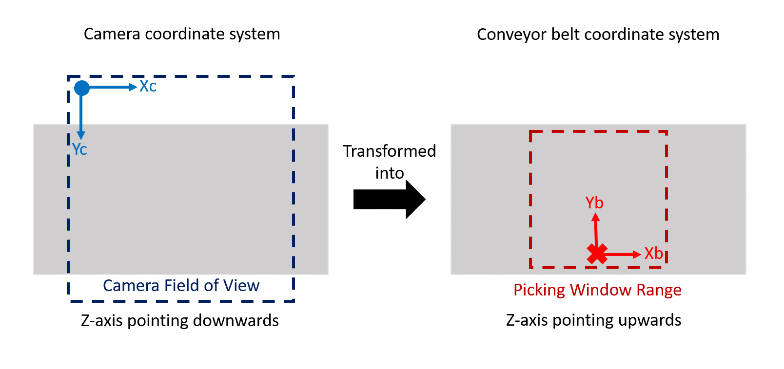
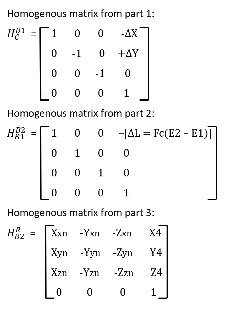
From the figure above, we can see that we need to do translation transformation in the X-axis and Y-axis to match the conveyor belt origin. For the Z-axis, the belt origin is facing the opposite direction of the camera origin which means we need to do rotation transformation. To summarize, we have 2 transformations in this part which are Translation in X-axis and Y-axis, Trans(ΔX, ΔY, 0); AND Rotation transformation, Rot(x, 180°). Notice that when we rotate in the X-axis, both Y-axis and Z-axis changed their facing direction. We will need to do some offset for this part.
Lastly, we also need to change the Pixel values from the camera coordinate to Real distance values. This means that we need to do camera calibration to correctly map the pixel values to distance values. You can read the rest about this here and here.
(Note: To determine the orientation of the origin/transformation, we need to refer to the right hand rule of coordinate system. This will help you to identify where is your XYZ axis direction should point to. We also have the right thumb rule for the rotation direction.)
2. Conveyor belt (B1) to Conveyor belt (B2) Transformation
For this part, it is quite simple. This transformation is about the movement of the conveyor belt from the Camera’s Field of view to the Robot’s Workspace/Pick range. The only value that change in this transformation is only the X-axis value. As per mentioned in the introduction, we also include the encoder’s reading to helps us track how much the distance has the conveyor belt covered.
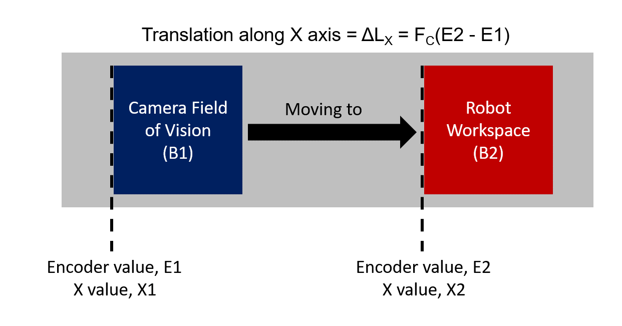
Where Fc stands for encoder’s factor that describes how much the distance the belt has travelled from the encoder’s impulses. We can get Fc from the equation below:
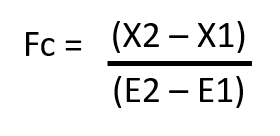
X2 - X1 = Distance between camera FOV and Robot’s workspaceTo summarize, the only transformation in this part is only in X-direction, Trans(ΔLx = Fc[E2 - E1], 0, 0)
(Note: You might be thinking, “Where is the tracking part?“. The answer lies in the value of the encoders, E1 & E2. To track them in real time situation, we need to get these encoder values and find the difference between the encoder value when the object is first detected by the camera with the current value of the encoder. We should name this variable as “Delta E”. From there, we can track the X-values of the object relative to the robot’s base frame.)
3. Conveyor belt (B2) to Robot Transformation
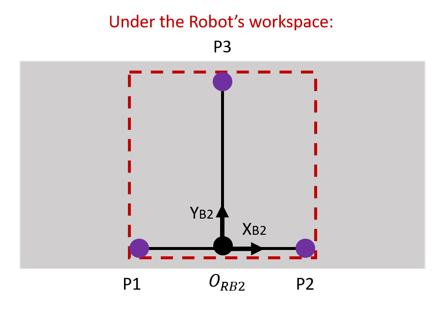
This part is quite complex and long, but please bear with me. To get homogenous transformation matrix between the conveyor belt (B2) and the robot frame, we need to use the ”3-Points Calibration Method”. This method is widely used in belt tracking system and considered a reliable method. You can read the rest about this method here and here. Basically, you need to write down the coordinate values of the robot base frame when the robot points towards 3 specific points on the conveyor belt.

The full procedure is explained below:
- To proceed, first we need to have 2 workpieces to be put on the conveyor belt. The workpiece can be anything as long as it is something that can be picked/tracked by the robot. In this project, the best item as the workpiece is something small to imitate the real foreign object.
- Place Workpiece 1 on the edge of one side of the conveyor belt. Start the conveyor belt until Workpiece 1 enters the working area of the robot (refer Figure 7). Stop the conveyor belt.
- Manually jog the robot end-tool tip to the grasping/sucking position of the workpiece. Record the coordinate values of the robot, P1. Remember, all the coordinate points have 3 members, X, Y and Z values.
- Restart the conveyor belt until the Workpiece 1 reaches the end of the picking range of the robot. Stop the conveyor belt and manually jog the robot to reach Workpiece 1. Record the coordinate values of the robot, P2.
- Remove Workpiece 1 and put Workpiece 2 at the opposite side of the Workpiece 1 (Refer to figure 7). Start the conveyor belt until Workpiece 2 reaches at the middle of the robot’s workspace.
- Stop the conveyor belt and manually jog the robot to reach Workpiece 2. Record the coordinate values of the robot, P3.
- Voila, you are done. Now for some mathematical derivation.
After this is completed, you will have 3 coordinate values which are P1= (X1, Y1, Z1), P2 = (X2, Y2, Z2) and P3 = (X3, Y3, Z3). All these values are important for us to find ORB2, which is the origin of the belt under the Robot’s workspace. From this ORB2, we need to create vectors with respect to the Robot’s base frame that is by the end of this process, we would get our homogenous transformation matrix for this part.
The equations to get ORB2 are as follow:

Once we get our ORB2, we can get the respective vectors, vectors magnitudes and unit vectors:
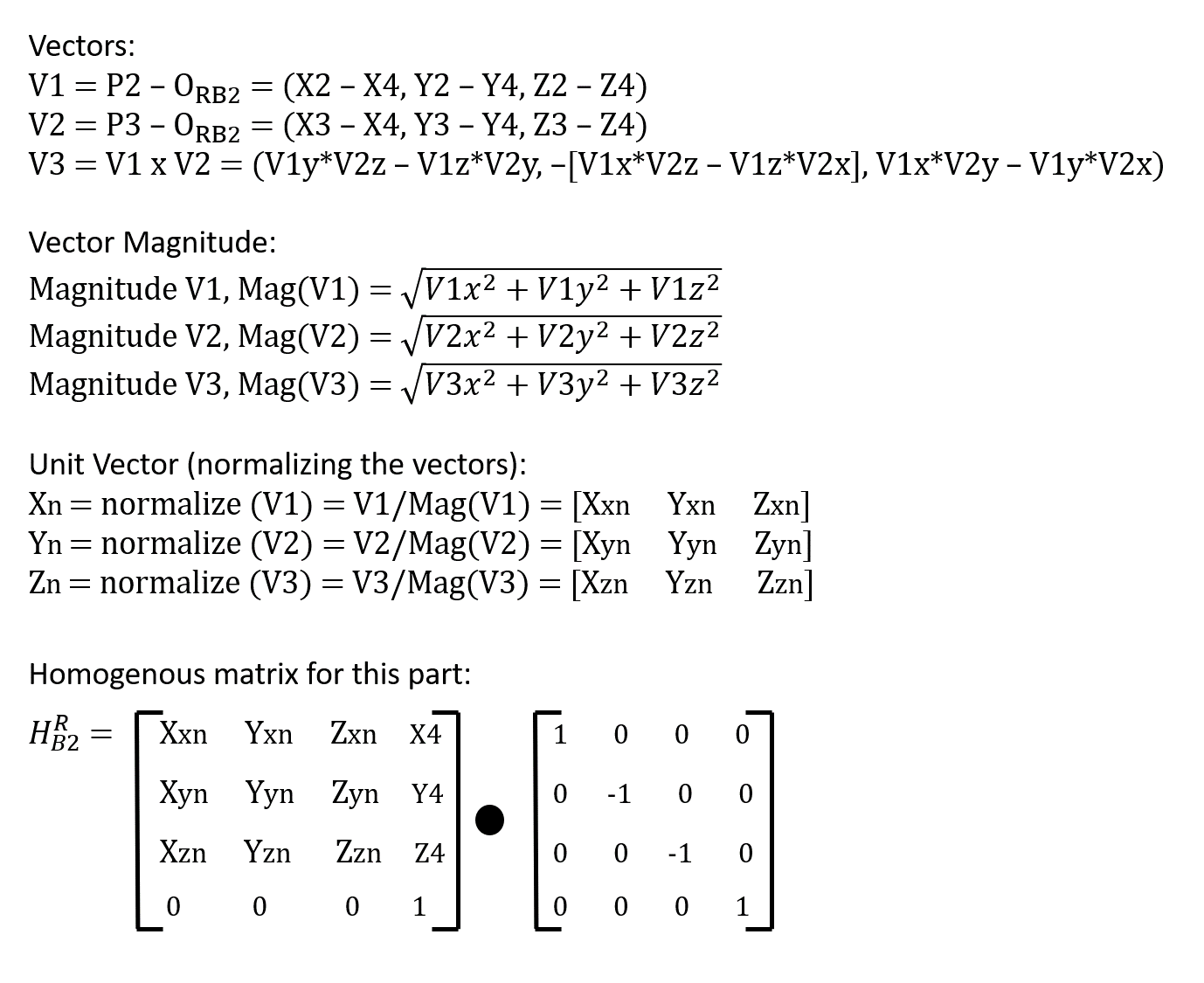
And finally, we get our homogenous transformation for this part. The reference for this method is here.
(Note: The extra matrix needs to be multiplied with our homogenous matrix to offset the rotation transformation that we have done during the calibration process.)
FINAL DERIVATION OF EQUATION + CHECKING
Since we have all the parts/equations needed, we can proceed with the final derivation. The final equation will combine all the homogenous matrixes that we’ve got from the previous section. The summary of the equations could be seen below:
Which yields our final equation to be:
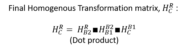
Now, we need to check the position of a point in Camera coordinate, PC with respect to the Robot’s base frame coordinate, PR. To get real-time position of a point from the Camera coordinate to the Robot coordinate, we just need to do a simple dot product using our hardly-earned derived matrix. The equation is as below:

I have created a spreadsheet that you can play around with if you’re interested. The link can be found here. Just change the PC values in the blue cells and you can see the change in the PR values.
CONCLUSION
With that, I have covered all the parts needed to develop a conveyor belt tracking system. A warning though; this whole system is not tested with real robot yet, only with simulation. I might make some updates regarding this for corrections etc.I’m sorry for the super long post but I can’t help it since there are some mathematical stuffs that need to be covered. Thank you for your patience and have a nice day!